Showing posts with label Fiber Optics. Show all posts

RAYLEIGH SCATTERING DEFINED AND TUTORIAL BASICS


What is Rayleigh Scattering?
Rayleigh Scattering Explained.

As a light pulse traverses the optical fiber, a small percentage of the light is scattered in all directions by the collision of photons with the materials that make-up the transmission medium, at the molecular level.

This phenomenon is called Rayleigh scattering. Rayleigh scattering is the primary source of power loss in optical fiber, accounting for well over 95% of the total light lost, extrinsic factors aside. In simple terms, as light propagates in the core of the optical fiber it interacts with the atoms in the glass structure in a complex manner depending upon the energy of the light (i.e., wavelength) and the size of the particles in the specific material or materials used in the waveguide.

Under certain conditions, photons may elastically collide with the atoms in the fiber matrix and be scattered as a result. Attenuation occurs when light is scattered at an angle that does not support continued propagation in the desired direction.

The lost light is either diverted out of the core or reflected back to the transmitter source. Less than 1% of the scattered light is reflected back, or “backscattered,” toward the transmitter source, and it is this effect that forms the basis by which optical time domain reflectometers (OTDR) operate.

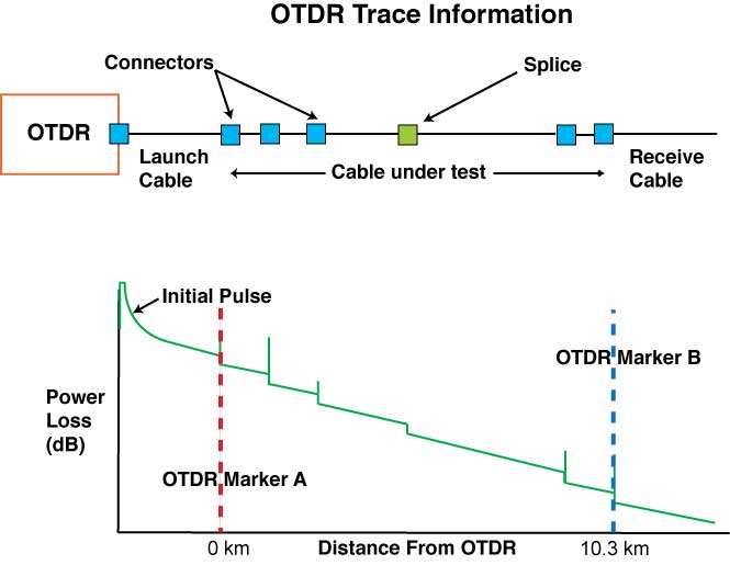
The OTDR is an important tool in fiber optics and is the piece of equipment most commonly used for testing and troubleshooting fiber optic systems. A characteristic OTDR trace is provided below.


Because the reflected light comes from the light pulse the original pulse power decreases, adding to the total attenuation before it reaches the receiver. The slope of the OTDR trace represents the attenuation coefficient of the fiber for the particular wavelength of light being transmitted.

The trace appears essentially straight, barring isolated events, because the overall attenuation coefficient of the fiber, which includes the Rayleigh backscatter coefficient, is assumed to be constant.

OPTICAL FIBER (FIBER OPTICS) TELECOMMUNICATION SYSTEM BENEFITS AND ADVANTAGES BASICS


What are the Benefits of Optical Fiber Telecommunications Systems?
Advantages of Optical Fiber Telecommunications System.


Optical fiber provides many fundamental advantages over alternative transmission technologies for telecommunications applications. The comparatively limited performance of copper conductor based systems forces the use of expensive signal conditioning and regeneration equipment (e.g., amplifiers and repeaters) at much closer intervals than for fiber optic systems. 

A single line of a voice grade copper system (i.e., 56 kbs) longer than a couple of kilometers requires the use of in-line signal processing for satisfactory performance, and even then is subject to the electromagnetic effects of interfering radio frequency sources such as radio, television, cell phone, and air traffic control broadcasts.

As information throughput requirements increasewith the demands ofmore data-intensive applications at the end-user premises, the spacing between the copper-based repeater points must decrease in order to maintain the same aggregate data rate capability over a given length. 

Contrast that to all-optical systems in which it is not unusual to transmit 10 gigabits per second data rates over hundreds of kilometers without the need for active signal processing between the transmitter and receiver.

Additionally, as it becomes necessary to increase the data transmission capacity or coverage area of a telecomunications system, the diameter and weight of cables for copper conductor systems increase much more rapidly than for optical fiber systems, resulting in a proportionally higher increase in materials, installation, and maintenance related costs.

The small size of optical cables, coupled with readily available components that make efficient use of the optical fiber’s transmission capabilities, enable them to be manufactured and installed in much longer lengths than copper cables. The virtually unlimited capacity of optical fiber also alleviates fears of incurring significant long-termcosts associated with frequent system upgrades, extensions, or over builds.

The availability of long lengths of individual lightweight fiber optic cables, up to 10 km or more, also make the installation of fiber optic systems much safer, easier, and less expensive, than comparable copper-based systems. Because of their design, fiber optic cables can generally be installed with the same equipment historically used to install twisted pair and coaxial cables, allowing some consideration for the smaller size and lower standard tensile strength properties of fiber optic cable.

More importantly, fiber optic cable design has progressed to the point where it serves as an enabling technology for newer installation methods that are faster, less expensive, and less intrusive to the environment than traditional installation means. 

Optical cables can be installed in duct system spans of 4000 meters (m) or more depending on the condition, construction, and layout of the duct system, and the details of the installation technique(s) used. Even longer lengths of fiber optic cable can be installed aerially, trenched, or buried in the ground and ocean floor. 

These extra-long lengths of cable reduce the number of splice points, thereby making the overall installation of optical fiber based telecommunications systems more efficient. The small size of fiber optic cable also saves on valuable conduit space in buried duct applications. 

This feature becomes even more prevalent when considering some emerging cable types that are specifically designed for use with air-blown or air-assist installation techniques into miniature ducts that are only about one centimeter in diameter.

Another advantage of optical fiber and fiber optic cable is the inherent flexibility in design options, allowing for the development of innovative products for specific applications. Since optical fiber is a man-made composite glass structure, it can be custom designed to meet optimal cost/performance targets in any number of specific applications. 

As it does not conduct electrical current and is not affected by electromagnetic interference, fiber optic cable can be made all dielectric, making it the ultimate in electromagnetically compatible transmission media. 

This eliminates such issues as dangerous ground loops, the effects of voltage spikes from the cycling of heavy electrical equipment, and requirements for separate conduits for metallic conductors. It also improves the security of controlled transmission rooms as it is much more difficult to tap a fiber optic line, andmuch easier to provide security for fiber optic cable.

FIBER CLADDING AND COATING BASIC INFORMATION


Fiber Cladding
The cladding is the layer of dielectric material that immediately surrounds the core of an optical fiber and completes the composite structure that is fundamental to the fiber’s ability to guide light. The cladding of telecommunications grade optical fiber is also made from silica glass, and is as critical in achieving the desired optical performance properties as the core itself.

For optical fiber to work, the core must have a higher index of refraction than the cladding or the light will refract out of the fiber and be lost. Initially multiple cladding diameters were available, but the industry swiftly arrived at a consensus standard cladding diameter of 125 μm, because it was recognized that a common size was needed for intermateability.

A cladding diameter of 125 μm is still the most common, although other fiber core and cladding size combinations exist for other applications. Because of their similar physical properties it is possible, and in fact highly desirable, to manufacture the core and cladding as a single piece of glass which cannot be physically separated into the two separate components.

It is the refractive index characteristics of the composite core-clad structure that guide the light as it travels down the fiber. The specific materials, design, and construction of these types of optical fibers make them ideally suited for use in transmitting large amounts of data over the considerable distances seen in today’s modern telecommunications systems.

Fiber Coating
The third section of an optical fiber is the outer protective coating. The typical diameter of an uncolored coated fiber is 245 μm, but, as with the core and cladding, other sizes are available for certain applications.

Coloring fibers for identification increases the final diameter to around 255 μm. The protective coating typically consists of two layers of an ultraviolet (UV) light cured acrylate that is applied during the fiber draw process, by the fiber manufacturer.

The inner coating layer is softer to cushion the fiber from stresses that could degrade its performance, while the outer layer is made much harder to improve the fiber’s mechanical robustness. This composite coating provides the primary line of physical and environmental protection for the fiber.

It protects the fiber surface to preserve the inherent strength of the glass, protects the fiber from bending effects, and simplifies fiber handling. The colored ink layer has properties similar to the outer coating, and is thin enough that its presence does not significantly affect the fiber’s mechanical or optical properties.

RAYLEIGH SCATTER FIBER OPTIC LOSS BASIC INFORMATION AND TUTORIALS


This is the scattering of light due to small localized changes in the refractive index of the core and the cladding material. The changes are indeed very localized.

We are looking at dimensions which are less than the wavelength of the light. There are two causes, both problems within the manufacturing processes.

The first is the inevitable slight fluctuations in the ‘mix’ of the ingredients. These random changes are impossible to completely eliminate. It is a bit like making a currant bun and hoping to stir it long enough to get all the currants equally spaced.

The other cause is slight changes in the density as the silica cools and solidifies. One such discontinuity is illustrated in figure below and results in light being scattered in all directions.


All the light that now finds itself with an angle of incidence less than the critical angle can escape from the core and is lost. However, much of the light misses the discontinuity because it is so small. The scale size is shown at the bottom.


The amount of scatter depends on the size of the discontinuity compared with the wavelength of the light so the shortest wavelength, or highest frequency, suffers most scattering. This accounts for the blue sky and the red of the sunset.

The high frequency end of the visible spectrum is the blue light and this is scattered more than the red light when sunlight hits the atmosphere. The sky is only actually illuminated by the scattered light.

So when we look up, we see the blue scattered light, and the sky appears blue. The moon has no atmosphere, no scattering, and hence a black sky.

At sunset, we look towards the sun and see the less scattered light which is closer to the sun. This light is the lower frequency red light.

ELECTROMAGNETIC SPECTRUM - CHOICE OF FIBER OPTIC FREQUENCY BASIC INFORMATION


Radio waves and light are electromagnetic waves. The rate at which they alternate in polarity is called their frequency (f ) and is measured in Hertz (Hz), where 1 Hz = 1 cycle per second.

The speed of the electromagnetic wave (v) in free space is approximately 3 X 10^8 ms–1. The term ms–1 means meters per second. The distance traveled during each cycle, called the wavelength ( ) can be calculated by the relationship:

wavelength = speed of light/ frequency


In symbols, this is: alpha =  v/ f


Electromagnetic spectrum
In the early days of radio transmission when the information transmitted was mostly restricted to the Morse code and speech, low frequencies (long waves) were used. The range of frequencies able to be transmitted, called the bandwidth, was very low. This inevitably restricted us to low speed data transmission and poor quality transmission.


As time went by, we required a wider bandwidth to send more complex information and to improve the speed of transmission. To do this, we had to increase the frequency of the radio signal used. The usable bandwidth is limited by the frequency used — the higher the frequency, the greater the bandwidth.


When television was developed we again had the requirement of a wider bandwidth and we responded in the same way — by increasing the frequency. And so it went on.

More bandwidth needed? Use a higher frequency. For something like sixty years this became an established response — we had found the answer! Until fiber optics blew it all away.

The early experiments showed that visible light transmission was possible and we explored the visible spectrum for the best light frequency to use. The promise of fiber optics was the possibility of increased transmission rates.

The old solution pointed to the use of the highest frequency but here we met a real problem. We found that the transmission losses were increasing very quickly. In fact the losses increased by the fourth power. This means that if the light frequency doubled, the losses would increase by a factor of 24 or 16 times.

We quickly appreciated that it was not worth pursuing higher and higher frequencies in order to obtain higher bandwidths if it meant that we could only transmit the data over very short distances. The bandwidth of a light based system was so high that a relatively low frequency could be tolerated in order to get lower losses and hence more transmission range.

So we explored the lower frequency or red end of the visible spectrum and then even further down into the infrared. And that is where we are at the present time. Infrared light covers a fairly wide range of wavelengths and is generally used for all fiber optic communications. Visible light is normally used for very short range transmission using a plastic fiber.


Windows
Having decided to use infrared light for (nearly) all communications, we are still not left with an entirely free hand. We require light sources for communication systems and some wavelengths are easier and less expensive to manufacture than others.

The same applies to the photodetectors at the receiving end of the system. Some wavelengths are not desirable: 1380 nm for example. The losses at this wavelength are very high due to water within the glass. It is a real surprise to find that glass is not totally waterproof.

Water in the form of hydroxyl ions is absorbed within the molecular structure and absorbs energy with a wavelength of 1380 nm. During manufacture it is therefore of great importance to keep the glass as dry as possible with water content as low as 1 part in 109.

It makes commercial sense to agree on standard wavelengths to ensure that equipment from different manufacturers is compatible. These standard wavelengths are called windows and we optimize the performance of fibers and light sources so that they perform at their best within one of these windows

The 1300 nm and 1550 nm windows have much lower losses and are used for long distance communications. The shorter wavelength window centered around 850 nm has higher losses and is used for shorter range data transmissions and local area networks (LANs), perhaps up to 10 km or so. The 850 nm window remains in use because the system is less expensive and easier to install.


HISTORY OF FIBER OPTICS IN COMMUNICATION BASIC INFORMATION AND TUTORIALS


How the use of fiber optics in electronic communications developed?

In 1880, only four years after his invention of the telephone, Alexander Graham Bell used light for the transmission of speech. He called his device a Photophone.

It was a tube with a flexible mirror at its end. He spoke down the tube and the sound vibrated the mirror. The modulated light was detected by a photocell placed at a distance of two hundred meters or so. The result was certainly not hi-fi but the speech could at least be understood.

Following the invention of the ruby laser in 1960, the direct use of light for communication was re investigated. However the data links still suffered from the need for an unobstructed path between the sender and the receiver. Nevertheless, it was an interesting idea and in 1983 it was used to send a message, by Morse code, over a distance of 240 km (150 miles) between two mountain tops.

Enormous resources were poured into the search for a material with sufficient clarity to allow the development of an optic fiber to carry the light over long distances.

The early results were disappointing. The losses were such that the light power was halved every three meters along the route. This would reduce the power by a factor of a million over only 60 meters (200 feet).

Obviously this would rule out long distance communications even when using a powerful laser. Within
ten years however, we were using a silica glass with losses comparable with the best copper cables.

The glass used for optic fiber is unbelievably clear. We are used to normal ‘window’ glass looking clear but it is not even on the same planet when compared with the new silica glass. We could construct a pane of glass several kilometers thick and still match the clarity of a normal window.

If water were this clear we would be able to see the bottom of the deepest parts of the ocean. We occasionally use plastic for optic fiber but its losses are still impossibly high for long distance communications but for short links of a few tens of meters it is satisfactory and simple to use.

It is finding increasing applications in hi-fi systems, and in automobile control circuitry. On the other hand, a fiber optic system using a glass fiber is certainly capable of carrying light over long distances.

By converting an input signal into short flashes of light, the optic fiber is able to carry complex information over distances of more than a hundred kilometers without additional amplification. This is at least five times better than the distances attainable using the best copper coaxial cables.

The system is basically very simple: a signal is used to vary, or modulate, the light output of a suitable source — usually a laser or an LED (light emitting diode). The flashes of light travel along the fiber and, at the far end, are converted to an electrical signal by means of a photo-electric cell. Thus the original input signal is recovered.

When telephones were first invented, it took 75 years before we reached a global figure of 50 million subscribers. Television took only 13 years to achieve the same penetration and the Internet passed both in only four years. As all three of these use fiber optics it is therefore not surprising that cables are being laid as fast as possible across all continents and oceans.

Optic fibers carry most of the half million international telephone calls leaving the US everyday and in the UK over 95% of all telephone traffic is carried by fiber. Worldwide, fiber carries 85% of all communications.

FIBER OPTIC CLADDING AND COATING DIFFERENCE BASIC INFORMATION


Fiber Cladding
The cladding is the layer of dielectric material that immediately surrounds the core of an optical fiber and completes the composite structure that is fundamental to the fiber’s ability to guide light. The cladding of telecommunications grade optical fiber is also made from silica glass, and is as critical in achieving the desired optical performance properties as the core itself.

For optical fiber to work, the core must have a higher index of refraction than the cladding or the light will refract out of the fiber and be lost. Initially multiple cladding diameters were available, but the industry swiftly arrived at a consensus standard cladding diameter of 125 μm, because it was recognized that a common size was needed for intermateability.

A cladding diameter of 125 μm is still the most common, although other fiber core and cladding size combinations exist for other applications. Because of their similar physical properties it is possible, and in fact highly desirable, to manufacture the core and cladding as a single piece of glass which cannot be physically separated into the two separate components.

It is the refractive index characteristic of the composite core-clad structure that guide the light as it travels down the fiber. The specific materials, design, and construction of these types of optical fibers make them ideally suited for use in transmitting large amounts of data over the considerable distances seen in today’s modern telecommunications systems.

Fiber Coating
The third section of an optical fiber is the outer protective coating. The typical diameter of an uncolored coated fiber is 245 μm, but, as with the core and cladding, other sizes are available for certain applications.

Coloring fibers for identification increases the final diameter to around 255 μm. The protective coating typically consists of two layers of an ultraviolet (UV) light cured acrylate that is applied during the fiber draw process, by the fiber manufacturer.

The inner coating layer is softer to cushion the fiber from stresses that could degrade its performance, while the outer layer is made much harder to improve the fiber’s mechanical robustness. This composite coating provides the primary line of physical and environmental protection for the fiber.

It protects the fiber surface to preserve the inherent strength of the glass, protects the fiber from bending effects, and simplifies fiber handling. The colored ink layer has properties similar to the outer coating, and is thin enough that its presence does not significantly affect the fiber’s mechanical or optical properties.

BENEFITS OF OPTICAL FIBER TELECOMMUNICATIONS SYSTEMS


Optical fiber provides many fundamental advantages over alternative transmission technologies for telecommunications applications. The comparatively limited performance of copper conductor based systems forces the use of expensive signal conditioning and regeneration equipment (e.g., amplifiers and repeaters) at much closer intervals than for fiber optic systems.

A single line of a voice grade copper system (i.e., 56 kbs) longer than a couple of kilometers requires the use of in-line signal processing for satisfactory performance, and even then is subject to the electromagnetic effects of interfering radio frequency sources such as radio, television, cell phone, and air traffic control broadcasts.

As information throughput requirements increase with the demands of more data-intensive applications at the end-user premises, the spacing between the copper-based repeater points must decrease in order to maintain the same aggregate data rate capability over a given length.

Contrast that to all-optical systems in which it is not unusual to transmit 10 gigabits per second data rates over hundreds of kilometers without the need for active signal processing between the transmitter and receiver.

Additionally, as it becomes necessary to increase the data transmission capacity or coverage area of a telecomunications system, the diameter and weight of cables for copper conductor systems increase much more rapidly than for optical fiber systems, resulting in a proportionally higher increase in materials, installation, and maintenance related costs.

The small size of optical cables, coupled with readily available components that make efficient use of the optical fiber’s transmission capabilities, enable them to be manufactured and installed in much longer lengths than copper cables. The virtually unlimited capacity of optical fiber also alleviates fears of incurring significant long-term costs associated with frequent system upgrades, extensions, or over builds.

The availability of long lengths of individual lightweight fiber optic cables, up to 10 km or more, also make the installation of fiber optic systems much safer, easier, and less expensive, than comparable copper-based systems.

Because of their design, fiber optic cables can generally be installed with the same equipment historically used to install twisted pair and coaxial cables, allowing some consideration for the smaller size and lower standard tensile strength properties of fiber optic cable.

More importantly, fiber optic cable design has progressed to the point where it serves as an enabling technology for newer installation methods that are faster, less expensive, and less intrusive to the environment than traditional installation means. Optical cables can be installed in duct system spans of 4000 meters (m) or more depending on the condition, construction, and layout of the duct system, and the details of the installation technique(s) used.

Even longer lengths of fiber optic cable can be installed aerially, trenched, or buried in the ground and ocean floor. These extra-long lengths of cable reduce the number of splice points, thereby making the overall installation of optical fiber based telecommunications systems more efficient. The small size of fiber optic cable also saves on valuable conduit space in buried duct applications.

This feature becomes even more prevalent when considering some emerging cable types that are specifically designed for use with air-blown or air-assist installation techniques into miniature ducts that are only about one centimeter in diameter.

Another advantage of optical fiber and fiber optic cable is the inherent flexibility in design options, allowing for the development of innovative products for specific applications. Since optical fiber is a man-made composite glass structure, it can be custom designed to meet optimal cost/performance targets in any number of specific applications.

As it does not conduct electrical current and is not affected by electromagnetic interference, fiber optic cable can be made all dielectric, making it the ultimate in electromagnetically compatible transmission media.

This eliminates such issues as dangerous ground loops, the effects of voltage spikes from the cycling of heavy electrical equipment, and requirements for separate conduits for metallic conductors.
It also improves the security of controlled transmission rooms as it is much more difficult to tap a fiber optic line, and much easier to provide security for fiber optic cable.
FIBER OPTICS IN COMMUNICATION HISTORY


HISTORY OF FIBER OPTICS USE IN COMMUNICATION

In 1880, only four years after his invention of the telephone, Alexander Graham Bell used light for the transmission of speech. He called his device a Photophone. It was a tube with a flexible mirror at its end. He spoke down the tube and the sound vibrated the mirror.

The modulated light was detected by a photocell placed at a distance of two hundred meters or so. The result was certainly not hi-fi but the speech could at least be understood.
Following the invention of the ruby laser in 1960, the direct use of light for communication was re-investigated. However the data links still suffered from the need for an unobstructed path between the sender and the receiver.

Nevertheless, it was an interesting idea and in 1983 it was used to send a message, by Morse code, over a distance of 240 km (150 miles) between two mountain tops.

Enormous resources were poured into the search for a material with sufficient clarity to allow the development of an optic fiber to carry the light over long distances.

The early results were disappointing. The losses were such that the light power was halved every three meters along the route. This would reduce the power by a factor of a million over only 60 meters (200 feet).

Obviously this would rule out long distance communications even when using a powerful laser. Within ten years however, we were using a silica glass with losses comparable with the best copper cables.

The glass used for optic fiber is unbelievably clear. We are used to normal ‘window’ glass looking clear but it is not even on the same planet when compared with the new silica glass. We could construct a pane of glass several kilometers thick and still match the clarity of a normal window.

If water were this clear we would be able to see the bottom of the deepest parts of the ocean. We occasionally use plastic for optic fiber but its losses are still impossibly high for long distance communications but for short links of a few tens of meters it is satisfactory and simple to use. It is finding increasing applications in hi-fi systems, and in automobile control circuitry.

On the other hand, a fiber optic system using a glass fiber is certainly capable of carrying light over long distances. By converting an input signal into short flashes of light, the optic fiber is able to carry complex information over distances of more than a hundred kilometers without additional amplification. This is at least five times better than the distances attainable using the best copper coaxial cables.

The system is basically very simple: a signal is used to vary, or modulate, the light output of a suitable source — usually a laser or an LED (light emitting diode). The flashes of light travel along the fiber and, at the far end, are converted to an electrical signal by means of a photo electric cell. Thus the original input signal is recovered.

When telephones were first invented, it took 75 years before we reached a global figure of 50 million subscribers. Television took only 13 years to achieve the same penetration and the Internet passed both in only four years.

As all three of these use fiber optics it is therefore not surprising that cables are being laid as fast as possible across all continents and oceans. Optic fibers carry most of the half million international telephone calls leaving the US everyday and in the UK over 95% of all telephone traffic is carried by fiber. Worldwide, fiber carries 85% of all communications.